featured image courtesy of freepik
Remote capsule microphones describe a broad class of devices that are designed with a condenser microphone capsule extended from its standard amplifier “microphone body”—which may be a phantom powered adaptor, wireless transmitter, or a low-voltage microphone input—by some length of cable. The remote capsule (or a mating coupling) must contain a minimal circuit to drive that relatively short length of cable from capsule to amplifier; whereas the amplifier body will contain the bulk of the circuit that must perform the tasks of regulating phantom power to the supplies required by the capsule, while amplifying the capsule signal to provide a balanced, low-impedance output capable of driving hundreds of meters of cable without signal degradation.
The small form factor of remote capsules allows mounting in placements that would not be possible for a full-sized microphone body. There are many applications for remote capsules, including lapel, podium, in-ear (binaural), suspended (“flown”), on-instrument, boundary, and any other application where size, weight, or visual profile must be minimized.
Due to the diverse portfolio of applications and solutions, each microphone manufacturer has developed its own standard for interconnection of remote capsules. Sound technicians, recordists, and third-party providers have invented still more custom solutions to realize even greater flexibility than designed by major manufacturers.
These options can be bewildering for the novice. This article will attempt to explain the technology common to various products and catalog many of the solutions available.
Condenser Microphone Types
First, let’s review how condenser microphones operate. “Condenser” is an older term for “capacitor”; the diaphragm and backplate of a condenser capsule form a capacitor together with the air gap between them. Acoustic vibrations cause the distance between the diaphragm and backplate to vary, changing the capacitance of the capsule. When charged, or “polarized”, that variation in capacitance will cause current to flow and thus an audio signal is generated.
The polarization charge is provided by one of two methods: a permanently polarized, or “electret” condenser capsule has the charged electret material affixed to the backplate. An externally polarized, or “true” condenser capsule (“true” being a misnomer, because both externally and permanently polarized capsules are capacitors), requires a voltage supplied to the capsule, which is applied either to the diaphragm or backplate. External polarization was the original condenser capsule technology, whereas the later electret technology has come to dominate the overall microphone market—an estimated one billion electret capsules are manufactured each year!
Either capsule type has the critical characteristic of very high source impedance, on the order of several megaohms (the capsules will have capacitance in the picofarad range). In order to avoid signal degradation, an amplifier must be located as close as possible to the capsule. While the first condenser microphones used vacuum tubes (valves)—which is still a popular choice for full-size studio microphones—the solution in remote capsules is a junction gate field effect transistor (JFET) amplifier located either inside the capsule or as part of a coupling that directly affixes to the capsule, and is thus part of the extended housing remote from the microphone’s amplifier body.
Since a JFET is an active device, it also requires a voltage supply for powering. So a remote capsule microphone solution will either one or two voltage supplies, a low-voltage supply for the JFET (typically between 1.5V and 20V) for all remote capsules; and for an externally polarized capsule, a high-voltage polarization supply (typically between 40V and 60V). A few remote solutions generate the high-voltage supply from the low-voltage JFET supply using a conversion circuit that is inside the remote capsule (or capsule coupling) housing, but most require separate voltage supplies.
The JFET voltage range is generally not too critical, provided that the maximum voltage rating for the JFET is not exceeded (not all manufacturers provide that specification, but up to 10V should be tolerated in nearly all devices). However, at the lower end of that range (under 3V), the performance of the circuit may be impaired. Thus, 5V is commonly provided as a general solution, and the range of 5V to 8V is recommended. Some consumer recording equipment may provide only 3V, which may result in acceptable if suboptimal performance—especially on very loud sources.
Polarization Voltage
While the JFET supply voltage may range with little change in specification, the polarization voltage has a direct effect on circuit performance. The sensitivity of the capsule varies according to polarization voltage. A higher voltage will yield a higher signal output for a given acoustic input (the capsule’s “sensitivity”). Using the formula for decibel reference, for example, comparing 40V with 60V polarization:
dB = 20 * log ( 60V / 40V ) = +3.5dB
That 3.5dB difference impacts several performance specifications: sensitivity, self-noise, and maximum SPL handling. That is, the higher polarization voltage has higher sensitivity, lower self-noise, and lower SPL handling.
Each manufacturer has specified their product with a selected polarization voltage. While this is generally not a critical specification, care should be taken to not provide a higher than specified voltage, because the internal circuit of the capsule may not be rated for a voltage that greatly exceeds that specification.
On the other end, using a lower than specified polarization voltage has the potentially useful characteristic of lowering the capsule sensitivity. This can be helpful when recording very loud sources; for example, close microphone placement on drums. If a capsule is specified at 60V with maximum SPL handling of 132dBSPL (which can be exceeded in that application), reducing the polarization voltage to 15V will reduce sensitivity and increase SPL handling by 12dB:
dB = 20 * log ( 15V / 60V ) = -12dB
Note that also increases self-noise by 12dB, so this technique would only be indicated for very loud sources.
Circuits for Remote Capsule Microphones
We have seen that a remote capsule electret microphone will require a low-voltage supply as well as a signal output, and of course a ground reference. The power supply and signal may be combined on a single lead by providing the JFET voltage across a supply resistance. Thus, there are two basic options for JFET circuits:
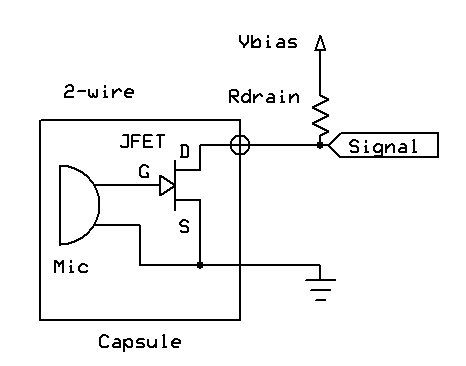
“Two-wire”: a single lead for combined power and signal, plus ground reference, formally called common source:
“Three-wire”: separate leads for power, signal, and ground reference; formally called source follower, or common drain:
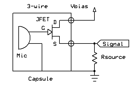
Each circuit has its advantage: two-wire can use a smaller-diameter cable; three-wire can have lower source impedance and thus can be somewhat more resistant to induced interference.
Some other considerations in JFET circuits are biasing, gain, and balanced signal transmission.
Proper biasing is critical for maximizing JFET circuit performance. In order to minimize distortion and noise, and thus maximize dynamic range, the JFET’s gate bias must be critically set. Depending on the circuit topology, the bias-setting components can be internal to the remote capsule circuit, external to the remote capsule circuit but non-critical, or a critical external bias circuit.
This is generally not a concern when utilizing a single manufacturer’s system as designed, but when developing or utilizing custom solutions, the manufacturer’s specification for external circuit components must be closely followed. This is especially critical when changing the circuit topology of a microphone; for example, when operating a three-wire capsule in two-wire mode.
The external source resistor commonly used in three-wire circuits is usually not critical (unless that resistor sets the JFET bias), but as with supply voltage, may be selected within a wide range with little change in performance. This is especially true of three-wire electret capsules with internal JFETs. This table specifies dynamic range by source resistance and voltage for a typical three-wire electret capsule with internal JFET:
| Signal-to-noise ratio (dB) | ||||
| Voltage supply (Rload 5.6kΩ) | ||||
| Rsource | 3V | 5V | 8V | 10V |
| 3k9Ω | 78 | 79 | 79 | 79 |
| 4k7Ω | 78 | 79 | 79 | 79 |
| 5k6Ω | 76 | 78 | 79 | 79 |
| 10kΩ | 74 | 78 | 78 | 79 |
Performance will thus tend to degrade at a combination of lower voltages and higher resistance, as the JFET begins to get less bias current than it would like. At higher supply voltages, maximum signal-to-noise ratio can be maintained at any load.
Note that a characteristic of the source-follower circuit used in three-wire capsules is that circuit gain varies little as the load is changed, as the circuit operates near “unity”, or zero gain. Thus, the capsule output is nearly the same as the signal input from the capsule applied at the JFET gate:
Gain = Gm * Rsource / (1 + Gm * Rsource)
where Gm = JFET transconductance—typical values 0.5-3mS (milliSiemen); for this article, we will assume 1mS:
for Rsource = 2.2kΩ, Gain = (0.001S * 2200Ω) / (1 + 0.001S * 2200Ω) = 0.6875
dB = 20 * log (0.6875) = -3.3dB
for Rsource = 10kΩ, Gain = (0.001 * 10000) / (1 + 0.001 * 10000) = 0.9091
dB = 20 * log (0.9091) = -0.8dB
In contrast, component selection in two-wire circuits has several effects on circuit characteristics. The two-wire common source circuit depends upon selection of the supply resistance to determine the circuit gain and source impedance. Circuit gain is also a function of the JFET and its bias circuit—which is often simply a source resistor, but may be a grounded source. The latter approach is seen with inexpensive capsules, and while it yields maximum possible gain, typically has poor maximum SPL handling.
Thus, a two-wire microphone’s sensitivity cannot be defined without reference to the supply resistance of the powering circuit; the overall sensitivity will be the sum of capsule sensitivity plus common-source JFET gain. Given this formula for gain:
Gain = – Gm * Rdrain / (1 + Gm * Rsource)
(note that the negative term represents inversion of the signal at the gate)
for Rdrain = 10kΩ and Rsource = 2.2kΩ:
Gain = – (0.001S * 10000Ω) / (1 + 0.001S * 2200Ω) = -3.125
dB = 20 * log (3.125) = +9.9dB
for Rdrain = 10kΩ and source grounded:
Gain = – (0.001S * 10000Ω) / (1 + 0.001S * 0Ω) = -10
dB = 20 * log (10) = +20dB
for Rdrain = 2.2kΩ and Rsource = 10kΩ:
Gain = – (0.001S * 2200Ω) / (1 + 0.001S * 10000Ω) = -0.2
dB = 20 * log (0.2) = -14dB
It is thus possible to generate a wide range of output sensitivities, including attenuation, via selection of the supply resistance. The maximum amount of gain is constrained by the required bias current of the JFET circuit, which might range from 100μA to 2mA. If more gain is desired, the increase in supply resistance can be offset by a higher supply voltage, again within the constraint of the JFET voltage rating. However, the increase in supply resistance will also increase the circuit’s source impedance:
Zout = Rdrain
which will constrain the maximum cable length possible without unacceptable signal degradation:
Corner Freq (-3dB) = 1 / (2 * pi * Rdrain * F)
where F is the cable capacitance, possibly 300pF/m for a lavalier-type cable; for a 2m cable in a circuit with 10kΩ supply resistance:
Freq = 1 / (2 * pi * 10kΩ * 600pF) = 26.5kHz
Thus placing a practical limit on two-wire circuit gain and cable length. For this reason, the X-R remote capsule microphone system uses low-capacitance coaxial cable (65pF/m) such that its supply resistance of 6kΩ can support cables well in excess of the design limit of 5m (82kHz bandwidth).
Most three-wire capsules may be operated in two-wire mode by changing the circuit configuration. This requires the manufacturer’s specified bias circuit to be relocated within the reconfigured two-wire circuit, for example as part of a cable assembly:

Unbalanced vs. Balanced Capsule Outputs
Balanced signal transmission can provide strong rejection of induced interference. This becomes progressively more important as the required cable length is increased. Microphone source impedance is also a factor, but can be minimized with balanced transmission.
Relatively few remote capsule microphones are designed with balanced output circuits, and thus manufacturers generally specify cable lengths not to exceed 2m to 6m, with three-wire designs being more capable of the longer end of that range, due to the lower source impedance of that topology. For remote capsules that have a balanced output, cables up to 10m or more can be used with excessive signal degradation.
It is possible for some three-wire remote capsules to be operated in “pseudo-balanced” configuration. This is done by supplying its power lead with voltage across an external resistor, and treating that as the inverted signal lead, together with its noninverted signal lead into a balanced input amplifier. This configuration is sometimes called a phase splitter:
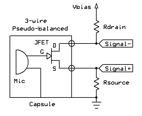
Since the impedance on that added signal lead will likely not exactly match the designated signal lead:
Zout- = Rdrain
Zout+ = Rsource / (1 + Gm * Rsource)
For Rdrain, Rsource = 2.2kΩ, and Gm = 1mS:
Zout- = 2.2kΩ
Zout+ = 2200 / (1 + 0.001 * 2200) = 688Ω
the common mode rejection of this ‘pseudo-balanced” circuit will not match a fully balanced output. Still, it is preferable to nothing, and in some circumstances may be enough to preserve signal integrity.
Externally Polarized Circuits
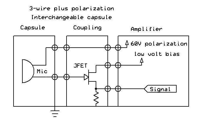
The options in JFET circuit configurations are the same in externally polarized capsules as for electrets, with a few distinctions. First, since most externally polarized capsules require a polarization voltage, there will be an extra lead to the capsule, such that the circuits will have three or four wires. To avoid confusion, these should be described as two-wire plus polarization and three-wire plus polarization.
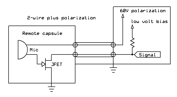
Second, the type of JFET most often used in externally polarized capsule circuits requires a different biasing mechanism. JFETs commonly used in electret capsules have an integral body diode which can “self-bias” the JFET tolerably across a range of source resistance; those JFET types are generally not seen in externally polarized capsule circuits. Thus, an externally polarized capsule will usually have a specific bias circuit that is critical for circuit performance. Some such remote capsules are designed with that bias circuit internal to the capsule, so that is not an issue for interconnection to custom solutions. However, in other cases, external components must be selected to match that manufacturer’s specification.
Lastly, many manufacturers of externally polarized remote capsule systems have their circuits entirely external to their capsules (which are often part of an interchangeable capsule system, either for mounting on a microphone body or remote applications). The required JFET circuit is located in a small coupling that affixes to the interchangeable capsule. Since the capsules themselves are simply capacitors, they can be used with any type of external circuit—provided that the remote housing is manufactured to meet the capsule’s mechanical specification. It is therefore possible to use one manufacturer’s capsules with another manufacturer’s remote system accessories using custom solutions.
Naiant Solutions for Remote Capsule Systems
Naiant’s microphone product line is designed as a remote capsule system. Both the X-X extended lead microphone and the X-R interchangeable capsule microphone system have a full range of mounting solutions for remote use.
Naiant’s range of inline devices is designed to provide support for nearly every other manufacturers’ remote capsule systems, whether permanently or externally polarized. The PFA phantom power adaptor and IFA inline amplifier can be configured for unbalanced or balanced, inverting or noninverting input. They provide a regulated JFET supply voltage from 5V to 16V and can optionally provide either an unregulated or regulated polarization voltage. The unregulated polarization voltage will vary with the supplied phantom voltage; for example, it will be approximately 40V with a 48V phantom supply, and 12V with a 15V supply. Thus, when used with a microphone amplifier that has a selectable phantom voltage, a PFA with unregulated polarization voltage will yield two sensitivity levels for the connected capsule, enabling use of the lower phantom voltage as a capsule attenuator. The fixed polarization voltage circuit option will generate the required voltage (between 40V and 60V) from any phantom supply voltage.
Naiant’s IPA flexible power amplifier can also support any remote capsule microphone that requires a JFET supply voltage up to 16V, and may optionally include a fixed polarization voltage circuit between 40V and 60V. With the IPA, remote capsule microphones may be powered from phantom, internal, or external battery supplies, providing the most flexible and configurable remote capsule amplifier solution available.
Catalog of Remote Capsule Systems
AKG® produces a range of wireless lapel microphones that use the Switchcraft® Q-G series “mini-XLR” connectors—TB3M for the transmitter, and TA3F for the microphone. This is a three-wire configuration. AKG has also produced full-sized microphones with interchangeable capsules that are capable of remote operation: the permanently polarized CK_X series. There are third-party solutions available for AKG’s CK 6_ capsules, including a limited production run of Naiant remote capsule couplers built from 2013 to 2014.
Audio-Technica® produces perhaps the widest range of permanently polarized remote capsule microphones, in two series. A-T’s Unipoint® installed sound series uses Switchcraft Q-G connectors (TB3M and TA3F, as with AKG), and their wireless series uses a latching 4-pin Hirose® connector. Either series uses a three-wire configuration.
Audix® supplies their wireless system microphones with either a TA3F or TA4F connector for compatibility with various systems. Audix also manufactures a miniaturized microphone series that is directly phantom powered (and thus not a remote system), the second smallest such microphone—smaller than the Schoeps CCM series, but not as small as the Naiant X-S!
Beyerdynamic® has a range of permanently polarized remote microphones in their TG wireless series, as well as a discontinued externally polarized remote capsule microphone, the CK930 (a three-wire plus polarization design).
Busman™ offers an externally polarized remote capsule microphone, the BSC2, which is a three-wire plus polarization design using Switchcraft Q-G series TA4F and TB4M connectors.
Countryman® manufactures one of the most popular lapel microphones for stage use, the B3, as well as several other remote headworn and instrument-mount models. Theirs is a two-wire design with several options for termination to interface with other manufacturer’s wireless transmitters, and with the widest range of color offerings to match different skin tones.
DPA® also commands a significant portion of the stage market with its wireless range. DPA’s lapel microphones use a two-wire design terminated with a Microdot 10-32, a small threaded coaxial connector.
Lectrosonic® offers a range of microphones for its wireless transmitters, using Switchcraft Q-G TA5F and TB5M connectors. Lectrosonics has had two revisions of its receiving circuit, both designed to operate the microphones in a two-wire configuration, but due to the flexibility of its system, the microphones can also support three-wire operation.
MBHO® produces an externally polarized remote capsule microphone, the MBP 603A. It uses a Switchcraft Q-G TA4F connector on the capsule, and a TB4M on its standard microphone body. The 603A is thus unique among externally polarized remote capsule microphones in that the capsule can either mount directly on the microphone body, or be extended with a simple TA4F to TA4M cable. The 603a capsule also features a balanced output!
Milab® supplies its VM44 microphone in a “Link” version, that extends the capsule using a Binder® 719 series five-pin connector. It is a three-wire plus polarization, balanced output circuit.
Naiant™ offers the X-X extended lead microphone, designed for lapel, binaural, or instrument mount applications, and available in a wide range of terminations to support most other manufacturers’ systems. In its XLR output configuration, the X-X capsule is pseudo-balanced to the powering circuit inside the XLR connector, offering good rejection of interference. For other terminations, the X-X can support two-wire, three-wire, or pseudo-balanced configurations. The Naiant X-R system uses standard RCA connectors to simplify extension from either its standard microphone body or remote cable. The X-R capsule is a two-wire design that can also interface with many other manufacturers’ systems. The X-Y flexible power amplifier can support from one to four X-R capsules via phantom, internal battery, or external power.
Neumann® has an externally biased remote capsule microphone system based on its KM100 amplifier, which used a three-wire plus polarization configuration. Uniquely, it supplied a negative voltage to its capsule—a positive voltage can be used instead, but will invert polarity from Neumann’s original design.
Schoeps® was the first to manufacture an externally polarized remote capsule system as part of their Colette series—and still offers the widest range of solutions, not only for capsule types, but also for remote amplifier and mounting options. Their KC cable accessory uses couplings to extend the MK series capsules from a CMC amplifier; while their KCY cable connects two MK series capsules to a single stereo input on a Binder 711-series 5-pin connector. The KCY was designed to connect to the VM microphone amplifier, but is also supported by third-party manufacturers, including Naiant. Schoeps also produces their CMR amplifier, which interfaces the MK capsules to other manufacturer’s wireless transmitters. The CMR is unique in that it is designed to be powered by the typical 5V offered by wireless transmitters, and has an internal circuit to generate the required polarization voltage. Finally, Schoeps offers its CCM microphone range, which while not truly a remote capsule system (as it contains a completely phantom powered circuit with balanced, low impedance output), is comparable in size to similar remote capsule solutions.
Sennheiser® produces a full range of permanently polarized remote capsule microphones, including the popular MKE2 for their wireless series, using a Switchcraft latching 3.5mm miniplug connector in a two-wire configuration.
Shure® manufactures a full range of permanently polarized remote capsule microphones for their wireless series, using Switchcraft TA4F and TB4M connectors in a three-wire configuration.
Soundblaster®-compatible microphone inputs for PCs use a three-wire unbalanced configuration for permanently polarized capsules, with a 5V FET supply using a 3.5mm minijack connector. Because the supply voltage is across a standard 2.2KΩ resistor, it is also possible to use two-wire microphones into a Soundblaster-compatible input by linking the tip and ring of the microphone’s miniplug connector.

