
The IPA was discontinued in February 2021.
IPA version 2 feature set:
- one to four channel input
- regulated +6 to +16V supply to connected microphones
- options for A23 or internal rechargeable Li-ion batteries
- +5-15V external battery jack or +12-48V phantom power via XLR or RJ45 output connector
- XLR-3-M (one or two channels), XLR-5-M (two to four channels), or RJ45 output (four-channel impedance-balanced output, without internal battery)
- seven gain settings (three settings for four-channel version)
- impedance- (one, two, or four channels) and electrically-balanced or transformer-coupled output options (mono and stereo only)
- high-efficiency polarization voltage circuit for “active” remote capsule microphones
- optional mid-side decoding/encoding circuit
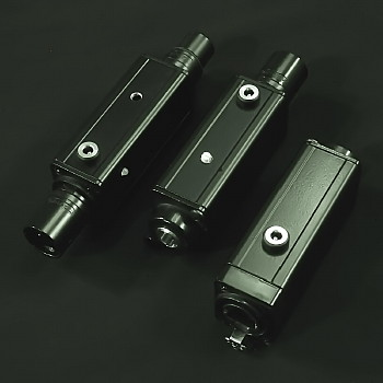
The IPA flexible power microphone amplifier is an inline amplifier, phantom power adaptor, and battery power supply that supports a wide range of microphones, including low-voltage and “active” remote capsule microphone systems. The IPA also offers a low-noise transformer-input version for dynamic ribbon and moving-coil microphones. The IPA is available in mono, stereo, and four-channel input configurations, including options for impedance- or electrically-balanced output, and mid-side encoded/decoded outputs.
Input polarity and output configuration
The IPA is available in a wide range of input connectors and may be customized as required for each microphone type.
In its basic format, each channel of the IPA is a single-ended noninverting amplifier with an unbalanced output. The IPA can support inverting input by either routing the output to an inverted output pin (with the IPA connected to a balanced input via an impedance-balancing XLR output cable), or with the electrically-balanced output option, in which additional amplifier channels are used to invert the signal such that both noninverting and inverting outputs are present. The electrically-balanced output option is limited to mono and stereo versions. Four-channel versions are noninverting, unbalanced output (except the RJ45 output version, which is four channel impedance-balanced output), which may be connected to a standard microphone amplifier input via impedance-balancing XLR output cables.
For stereo unbalanced microphones, the IPA can generate either an impedance-balanced (standard) or electrically-balanced (optional) output. The electrically balanced output has nominal +6dB gain into a standard differential input microphone amplifier, and requires two amplifier channels for mono and four amplifier channels for stereo.
The IPA can support balanced interconnection for any mono or stereo microphone via independent noninverting and inverting inputs. Note that an IPA in this configuration is not a differential circuit (and thus will not cancel interference by itself), but when connected to a standard differential input microphone amplifier will complete a fully balanced circuit from microphone to amplifier. Balanced input requires two amplifier channels for mono and four amplifier channels for stereo.
Differential balanced input to balanced or unbalanced output can be supported by the addition of input (mono only) or output (mono or stereo) transformers; please inquire for compatible configurations.
Input configuration
Low-voltage microphone input
Low-voltage microphones are wired as either two-terminal (signal + power and ground) or three-terminal (power, signal, and ground) devices. Most two-terminal microphones have a negative polarity output, while most three-terminal microphones have a positive polarity output. As noted above, an IPA may be configured to invert polarity for a stereo two-wire microphone to an unbalanced input, or via an inverting output cable to a balanced input device.
Some three-terminal low-voltage microphones may be connected to a balanced input IPA in a “pseudo-balanced” configuration–the impedance on each terminal may not exactly match, but this configuration can still offer some rejection of interference compared with the unbalanced three-terminal configuration. This “pseudo-balanced” configuration will be supplied with compatible microphone formats, including Audio-Technica TA3M and Shure TA4M formats, unless otherwise requested.
Dynamic microphone input
For dynamic microphones, the IPA offers a balanced input via a step-up (+9dB) input transformer. The dynamic microphone version is single input channel only. This version offers a low-noise, battery powered amplification solution with selectable gain for dynamic moving-coil and ribbon microphones. For phantom-powered operation only, without gain switching, the IFA offers a lower-cost and smaller solution.
3.5mm miniplug “plug-in power” microphones
Stereo “plug-in power” microphones are supported with a TB3M mini-XLR input connector. For superior reliability, the microphones should be directly terminated with a mating TA3F connector (pin 1, ground; pin 2, left; pin 3, right; or as specified). Alternatively, a 3.5mm minijack to TA3F adaptor cable [link custom cables] may be used. A four-channel IPA can support two stereo “plug-in power” microphone pairs via TB6M input using a dual stereo minijack to TA6F input adaptor cable.
There are several common methods of wiring input jacks for miniplug microphones, which are not fully compatible. The IPA can be supplied to support the following formats:
- Mono PC microphone (Soundblaster® format): tip = signal (6.8kΩ termination to ground); ring = power (+8V across 2kΩ); sleeve = ground. (maximum of three microphone input)
- Mono plug-in power (“PIP”): tip & ring = signal + power (+8V across 6.8kΩ); sleeve = ground. (maximum of four microphone input)
- Mono Sennheiser® compatible: tip = signal + power (+8V across 6.8kΩ); ring = no connection; sleeve = ground. (maximum of four microphone input)
- Stereo plug-in power (“PIP”): tip = left + power (+8V across 6.8kΩ); ring = right + power (+8V across 6.8KΩ); sleeve = ground. (maximum of two stereo microphone pair input)
Phantom power for microphones
An IPA can be configured to provide +12V or +16V phantom power (from a +48V phantom or internal Li-ion battery supply) to a connected microphone with limited current draw (3mA or less, two channel maximum). It is not possible for an IPA to supply +48V phantom power to a connected microphone.
tinybox format input
An IPA can be supplied with a TA6M connector in “tinybox” format input, as follows:
Pin:
- low-voltage supply (+6-16V) or right output
- right input (noninverting)
- left input (noninverting)
- polarization voltage (+60V max) or left output
- center/third channel input (noninverting), right input (inverting) or right output
- rear/fourth channel input (noninverting), left input (inverting) or left output
Chassis: ground
Each signal input pin may also provide a low-voltage microphone supply, as required.
In tinybox format, the IPA will have either an XLR-3-M (stereo unbalanced) or XLR-5M (stereo balanced or four-channel unbalanced) output connector. An IPA configured for stereo inverting input to noninverted output will require use of four amplifier channels, which will correspondingly increase current draw and reduce autonomy.
A single IPA can support multiple microphone types by providing two different low-voltage microphone supplies (on pin 1 and pins 2-3, 5-6), as was possible with a tinybox, with some limitations.
The IPA can be configured to support stereo input and output via the TB6M connector using a minijack & miniplug splitter cable.
All inputs may also have a low-voltage supply (+6-16V) across a specified resistance, or termination to ground as required. Polarization and low-voltage supplies may be customized as required by the connecting microphones’ specification. It may be possible to support multiple microphone types with a single IPA, depending on the exact requirements.
Custom input formats
The IPA is also available with custom input connections for a wide range of microphone types, including TB4M and TB5M, Binder series 711-5-F, and XLR-3-F, -5-F, or -6-F. Please inquire to verify custom configurations.
Custom features and gain
“Active” remote capsule microphones and polarization voltage
The IPA can support a range of “active” remote capsule, externally polarized condenser microphones that require a high polarization voltage. An IPA configured to support “active” remote capsule microphones contains a polarization circuit that outputs a fixed voltage (between +40V and +60V), as required by the microphone, at any phantom supply (+12-48V), internal battery, or external supply voltage.
Gain control
The IPA offers a seven-position switch (three-position for four channel input versions) for gain control. The gain switch may be set with either a spindle (shown) or a screwdriver slot (3mm flathead). Standard gain settings are from 0 to +18dB for the seven-position switch, and 0dB to +16dB for the three-position switch. If desired, mono and stereo versions may also be supplied with the three-position switch, and all versions may be built with fixed gain only. Custom gain settings may be selected within the +27dB maximum range.
Output level may be further increased by +6dB with the electrically-balanced output option (mono and stereo versions only).
The dynamic microphone input version has minimum gain of +9dB (due to the input transformer) and maximum available gain of +36dB (+42dB with electrically-balanced output).
Output configuration and polarity
The IPA is available with the following outputs:
- XLR-3-M: mono input, electrically-balanced or transformer-coupled output
- XLR-3-M: stereo unbalanced output
- XLR-5-M: stereo input, impedance-, transformer-, or electrically-balanced output
- XLR-5-M: stereo input with left-right and mid-side outputs (all unbalanced)
- XLR-5-M: four-channel unbalanced input to output
- RJ45 (cat 5e plus ground): four channel input to impedance balanced output (no internal battery)
Pin assignments by function are as follows (the +/- designation indicates the output polarity of the channel for a positive polarity input on all channels):
Output pin (XLR-5-M; -3-M)
- ground; ground
- left+; left+ or mono+
- left-, center+, or mid-; right+ or mono-
- right+
- right-, rear+, or side-
The IPA input is noninverting, and thus any direct channel output will also be noninverted. The optional XLR output cables may be configured to correct inverted inputs such that all channel outputs are noninverted.
Special amplifier functions
The IPA has two special amplifier functions that generate inverted outputs: electrically-balanced outputs (pins 3 and 5 inverted), and a mid-side encoder/decoder that will output both inverted, encoded outputs (pins 3 and 5) as well as noninverted, unencoded outputs (pins 2 and 4).
When operating on internal battery or external power, the IPA’s output may be directly connected to any stereo unbalanced input with an XLR to 3.5mm miniplug output adaptor cable. There will be no DC voltage present on the XLR output when operating on internal or external battery. Polarity inversion via output pin selection into an unbalanced input is possible for an IPA configured with an electrically-balanced stereo output, by using an XLR to 3.5mm miniplug output cable that is wired to the corresponding pins (2 and 4 for noninverting, or 3 and 5 for inverting).
Output cables
Special output cables containing impedance-balancing networks are available in these formats:
- XLR-3-F to dual XLR-3-M
- XLR-3-F to stereo XLR-5-M
- XLR-5-F to quad XLR-3-M fanout
- XLR-5-F to XLR-10-M extension
- XLR-10-F to quad XLR-3-M fanout
When used with the fanout cables, the extension cables enable impedance-balanced operation from the IPA through to XLR-3-M fanouts while minimizing overall cable mass.
When operating on phantom power, the IPA only requires phantom power on any single output pin (pins 2 through 5); any channels without phantom power present will still generate a signal output without any DC voltage present. Four-channel IPAs may require phantom power be present on two output pins for specified headroom.
Unbalanced output XLR to 3.5mm miniplug cables may also be ordered from the output cable menu. An IPA with TB6M connector may have both input and output on the TB6M connector; see pin configuration above.
RJ45 output option
The RJ45 output requires Category 5e cable with shield, connected to a compatible RJ45-input device. There is no internal battery option with the RJ45 input, so either phantom power or an external battery must be used.
With reference to a TB6M input connector, the pin assignments are:
- pin 3 output
- pin 3 impedance network
- pin 4 output
- pin 2 impedance network
- pin 2 output
- pin 4 impedance network
- pin 5 output
- pin 5 impedance network
Chassis: ground
The RJ45 output uses a Neutrik etherCON Category 5e connector. Neutrik etherCON Category 5e cables are recommended for the best possible connection and signal integrity.
Power options and indication
The IPA has a flexible power supply scheme that can support:
- +9-52V phantom power
- internal A23 battery (battery not included)
- internal rechargeable 3.7V Li-ion battery pack
- external battery via DC power port (+5V to +15V; +9V maximum to charge internal Li-ion battery)
The external power jack is 1.7mm ID, 4.0mm OD, center-positive.
The highest voltage supply will prevail between internal and external batteries. The IPA contains a voltage regulation circuit that will generate a fixed supply of +12V or +16V for the amplifier and +6-16V for the microphone circuitry from the battery voltage. The voltage regulation circuit is not installed for IPA versions using an A23 battery, thus, A23 battery versions are limited to +8V for the amplifier and microphone supplies (plus +60V polarization circuit if required). The voltage regulation circuit does not function when operating on phantom power.
The A23 battery is accessed by removing the thumbscrews and then the bottom panel of the case.
The IPA has a dual green/red LED to indicate power source: red for phantom power; green for internal or external battery; yellow for internal low battery condition. Note that if an external battery supply is used that is lower than the configured internal battery type (with the internal battery removed), the LED may indicate yellow. Thus, the LED cannot indicate external low battery condition.
The internal rechargeable Li-ion battery pack supplies 3.7V with 350mAh capacity. An external power supply or battery between +5-9V (+5V recommended) is required to activate the recharge circuitry. Charge time is approximately seven hours. The LED will indicate red while charging, and green when fully charged. The IPA with Li-ion battery pack is supplied with a USB charging adaptor cable.
The IPA circuit (except the dynamic microphone input version) monitors the current draw on its input connector. The IPA’s amplifier circuit and microphone power supplies will activate when a microphone is connected to its input. When the input is not connected, the amplifier circuit and microphone power supplies will shut down and the circuit will draw an idle current of 25-40μA.
The IPA for dynamic microphone input is configured such that the battery is not connected unless pin 1 is bridged to the IPA chassis at the input XLR-3-F connector. Thus, the battery will not be drained unless a microphone or cable with pin 1 to chassis termination is attached. Most dynamic microphones have an internal connection from pin 1 to chassis, so it is recommended that the IPA be directly attached to the microphone. If the IPA must be remote from the microphone, then the microphone cable must have its pin 1 bridged to the shell on its XLR-3-M connector.
If the IPA is not to be used for longer than a week, the A23 battery should be removed to prevent discharge. The internal rechargeable Li-ion battery pack is monitored by an internal charge regulation circuit, and thus may be left connected to an external power supply without damage from overcharging or loss of capacity. If the Li-ion battery pack is allowed to fully discharge, loss of battery life may be experienced. The Li-ion battery pack should be fully charged at least monthly.
IPA version 2 flexible power inline microphone amplifier specification
Type: inline battery- or phantom-powered adaptor and amplifier for dynamic, low-voltage, and “active” remote capsule microphones.
Phantom Power Input: +9-52V; +24V minimum required for +16V “active” microphones.
External Power Input: +5-15VDC; minimum +12VDC required when internal A23 battery installed for operation on external battery.
External Power Input, internal Li-ion battery: +5-9VDC; +5VDC recommended.
Voltage Supplied to Microphones (Vmic): low-voltage; +8V, “active”; +6-16V.
“Active” Polarization Voltage: +60V maximum
Current (Iamp), exclusive of microphone current draw (Imic): 1.2mA for mono or stereo unbalanced or impedance-balanced; 2.4mA for all other configurations.
Current, polarization circuit (Ipol): 1.2mA
(currents given as draw from microphone supply)
Step-up circuit efficiency: 70% typical
Calculation of autonomy (external or 3.7V Li-ion batteries):
Hours = (Pbatt * 70%) / ((Iamp + Imic + Ipol) * Vamp)
where Pbatt is battery capacity in watt-hours:
Pbatt (A23; 3.7V Li-ion): 500mWh; 1300mWh
Example for +8V stereo “active” microphones with +16V amplifier supply and +60V polarization circuit, unbalanced or impedance-balanced output, using 3.7V Li-ion battery:
Hours = (1300mWh * 70%) / ((1.2mA + 0.5mA * 2 + 1.2mA) * 16V) = 16.7 hours
Note that for A23 and 12V external batteries, efficiency is 90% for Vmic<12V.
Current (idle, input not connected): 25μA (40μA for A23 battery)
Current (Li-ion battery charging): 50mA maximum
Input Impedance: 6kΩ or as specified
Output Impedance: 75Ω (each pin); 150Ω (dual XLR stereo output cable)
Recommended Preamp Input Impedance: 1.5kΩ or higher
Maximum Input Level, +12V/+16V amplifier supply, 0dB gain, 1kHz @ 1% THD: +10dBV/+13dBV
Maximum Input Level, dynamic mic input, 1kHz @ 1% THD, 0dB gain: +4dBV (+1dBV with A23 battery)
Total Harmonic Distortion, 1kHz @ 0dBV output, 0dB gain: less than 0.005%
Total Harmonic Distortion, 1kHz @ 0dBV output, +27dB gain: 0.025%
Total Harmonic Distortion, transformer input, 1kHz @ 0dBV output: 0.01%
Total Harmonic Distortion, transformer input, 100Hz @ 0dBV output: 0.1%
Total Harmonic Distortion, transformer output, 1kHz @ 0dBV output: 0.1%
Total Harmonic Distortion, transformer output, 100Hz @ 0dBV output: 2.0%
Frequency Response, -0.3dB @ 20Hz, +18dB gain: 20Hz to 40kHz
Frequency Response, transformer input, 150Ω source: 30Hz to 20kHz
Frequency Response, transformer output: 30Hz to 20kHz
Equivalent Input Noise, electrically-balanced output: -122dBV unweighted, -125dBA
Equivalent Input Noise, impedance-balanced output: -124dBV unweighted, -127dBA
Equivalent Input Noise, low-noise dynamic microphone version: -127dBV unweighted, -130dBA
Weight: 100g (3.5oz)
Dimensions: 111mm x 32mm x 25mm (4 3/8″ x 1 1/4″ x 1″)
IPA version 1 specification (where different from version 2):
External Power Input: +9 to +15VDC; +12VDC recommended;
minimum +12VDC required when internal A23 battery installed
Current, polarization circuit: additional 1.5mA
Current (idle, input not connected): 40μA
Voltage Supplied to Microphones: +8V typical
Output Impedance, optional minijack: 600Ω (each pin)
Recommended Line Input Impedance; minijack output: 5kΩ or higher
Maximum Input Level, 1kHz @ 1% THD, 0dB gain, A23 battery power, 1kHz @ 1% THD: +8dBV
Weight (standard): 91g (3.2oz)
Weight (extended): 100g (3.5oz)
Dimensions (standard): 93mm x 32mm x 25mm (3 5/8″ x 1 1/4″ x 1″)
Dimensions (extended): 111mm x 32mm x 25mm (4 3/8″ x 1 1/4″ x 1″)
Notice of FCC compliance
Pursuant to section 15.103(h), the IPA is only intended to be operated on battery or phantom power. The IPA’s oscillator is disabled during operation with phantom power. It is thus exempt from Part 15 of the FCC rules. The IPA qualifies for exemption as the highest frequency generated by the device is less than 1.705MHz, and it may not be operated from the AC power lines. Use of an IPA that is operated from the AC power lines is strictly prohibited under Part 15.
